The main points of interest in the trigger pull/reset are illustrated in the following diagram.
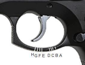
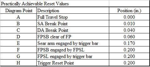
The marks (A, B, C, , H) represent the position of the tip of the trigger at various points in the trigger pull each point is described in the following table. Discussion lists values that represent a typical CZ75 DA/SA pistol.
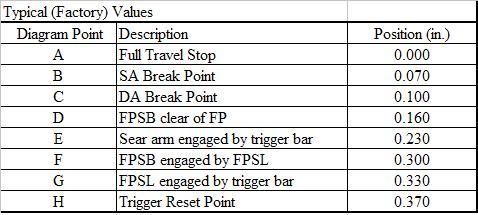
Each trigger position is marked in pencil on the trigger guard (similar to the above diagram). If extended, each mark would run from the tip of the trigger and cross the trigger guard perpendicularly at each labeled point. Using a caliper, distances are measured between the marks on the side of the trigger guard closest to the trigger. Values listed in the tables are given as distances measured from Point A.
To reduce reset, assess the actual travel between each of the above points and reduce unnecessary travel. CAUTION: Remember modifications in one area may affect others.
A-B Travel
Installing a trigger with an over-travel stop is the easiest way to reduce the trigger travel between points A and B. Alternatively one could delay the SA break point so that it is just 0.010 or so ahead of where the trigger contacts the frame at full travel.
B-C Gap
In order to function properly, the DA trigger must break slightly earlier in the pull stroke than the SA break point. The reason for this is that otherwise, when the SA sear releases the hammer, the DA disconnector would not be clear of the trigger bar and this would stop the hammer from falling. The typical value for this B-C gap is about 0.030 and this seems reasonable any more than this is probably a little excessive and might warrant reducing this gap (e.g. retard the DA break point by reducing the height of the leg on the disconnector). If this gap is less than 0.030 and the pistol functions properly and the SA trigger breaks cleanly (i.e. doesn't catch on the disconnector) then its probably fine as well. If this gap needs to be increased, one can consider delaying the SA break point be stoning material from the engagement face of the lower arm of the sear (this will close the A-B gap), or removing material from the bottom of the wings of the disconnector to advance the DA break point (this will close the C-D gap).
CD Gap
Before the hammer is released, the FPSB must be raised clear of the FP so that the hammer strike will launch the FP into the primer. Therefore, there must be some positive C-D gap. However, the 0.060 of gap in the typical set up illustrated can be trimmed considerably and reduce trigger travel and reset. This can be done by carefully stoning material from the engagement face of the lower arm of the FPSL. This must be done carefully, a little at a time, and checked frequently because if too much material is removed, the FPSB will not be released early enough and the gun may not fire. In this case, one must start with a new FPSL or reduce the height of the notch in the FP in which the FPSB sits (essentially reducing the engagement of the FPSB and FP).
This adjustment requires patience whereby you make small adjustments and checks the resulting C-D gap, frequently. Further, determining exactly where in the trigger pull the FPSB actually releases the FP is a little tricky you must cock the hammer and slowly and carefully pull the trigger while pushing on the (exposed) end of the FP with a small wooden stick (like a bamboo skewer). When the FPSB is clear of the FP, the FP will budge about and 1/8 or so. Note the position of the trigger at this point. Finally, to test that the FPSB really clears the FP in time, point the unloaded pistol at the ceiling, drop a pencil with a new eraser tip into the barrel (eraser end first) and pull the trigger. The pencil should fly at least a few inches indicating that it was struck by the FP (i.e. the FP was not blocked by the FPSB).
F-G Travel
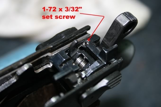
Ideally, when the slide is in battery, the top of the FPSL and the bottom of the FPSB should be in contact with each other so that as soon as the FPSL moves, the FPSB starts to rise. Conversely, any gap between these two parts when the slide is in battery leads to unnecessary trigger travel and reset. This can be remedied by installing a small set screw (or other suitable shim) in the ejector cage directly under the upper arm of the FPSL to shim this so it contacts the FPSB when the slide is in battery. The following photos show a 1-72 x 3/32 set screw serving this purpose. By carefully adjusting the set screw (shim height), the trigger travel/reset F-G can be reduced or eliminated.
G-H Travel
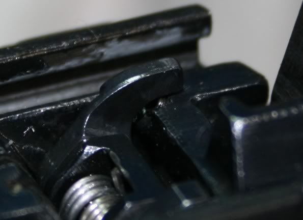
Ideally, the FPSL should be engaged as soon as the reset point is reached. In this case, the difference between these two points should be zero, instead of the 0.040 of slop in the typical stock value found above. The origin of this slop is in the geometry of the engagement faces of the trigger bar and lower leg of the FPSL. During the reset stroke, the trigger bar moves forwards to re-engage the lower FPSL arm. When the trigger bar clears the arm of the FPSL, it pops up and there will be a gap between the two if the engagement face geometry is angled shown in the following diagram. This leads to a crisp reset but the trigger travel G-H is required to close this gap (after reset) before the FPSL starts to move.
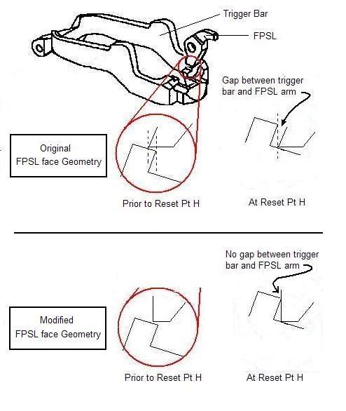
This gap can be eliminated/reduced by changing the angle of the face on the lower arm of the FPSL as shown in the lower part of the diagram. However, if the angle is changed too much, the crispness of the reset will be reduced or lost. By careful work, the travel G-H can be reduced/eliminated and still maintain a crisp reset. (NOTE: The above drawing is for illustration purposes only the angles of the faces are not necessarily representative of the actual faces. E.g. the modified face is shown perpendicular to the bottom edge of the FPSL arm and this is not necessarily the case.)
Optimal Reduced Reset Values
Based on the considerations outlined above, trigger travel/reset can be reduced (in the best case) to about 0.200. In this case, representative (reduced) trigger position at various points in the trigger pull (A, B, C, , H as above) are listed in the following table. In reality, one would be hard pressed to achieve all of the possible reset reduction outlined here and a reset in the neighborhood of 0.220" to 0.250" would be a more reasonable expectation in practice.
It should be noted that if not for the required engagement of the FPSB and FP, the shortest reset possible will be limited by the sear engagement point (0.170 in the above table based on typical factory sear/hammer engagement values). It is worth mentioning that removing the FPSB altogether (and modifying the FPSL to act as a spacer) should result in reducing the reset to this sear-limited value (and eliminates the need to address several of the more delicate issues discussed above). Further, reduction in sear/hammer engagement will further reduce the reset - using the CZ competition hammer and no FPSB, sub-0.100" reset is relatively easy to achieve and can approach half that amount with a little work. It should be noted, however, that very short reset such as this with relatively little sear-hammer engagement can lead to "doubling" whereby the movement of the gun in recoil can be enough to inadventently reset the trigger and break the next shot as the slide slams into battery.
Alternatively, one can shorten the reset to the limiting value of the factory sear/hammer engagement and still preserve most of the functionality of the FPSB by using the set screw discussed in "F-G Travel", above). In this case, the FPSL is raised (via the set screw) so that it partially raises the FPSB when the slide is in battery such that the lower arm of the FPSL lines up with the lower arm of the sear (and together they determine the (same) reset point). In the present (optimal) example, this will only reduce the engagement of the FPSB and the FP by about 20% ( = (0.200 0.170)/(0.200 0.060) = 0.030/0.140) and reduce reset to the sear engagement limited value.
In either case, it is assumed that the same considerations regarding the geometry of the engagement faces of the FPSL and trigger bar (addressed as above in G-H Travel) are applied to the engagement faces of the sear and trigger bar (i.e. one must address any "slop" introduced at the reset point as discussed in G-H Travel, above).

No comments:
Post a Comment